有许多人问我使用 Nios 的用户定义接口逻辑怎么用,想了几天决定设计一个实例来说明。
该例为一个使用 user to interface logic 设计的 PWM 实例,其中包括三个文件:
plus32.v 是一个为 32bit nios 设计的 pwm 实例。
plus16.v 是一个为 16bit nios 设计的 pwm 实例。
test.s是一个使用中断调用 pwm 的汇编语言测试程序。
以上模块和程序均调试通过,并可稳定工作。
这里让大家参考是使大家通过该例来真正理解 user to interface logic 设计方法,和nios 中通过汇编调用中断的方法,所以超值喔。另外热烈欢迎大家的指导。
注:在设计 Nios 时,将你调用的 user to interface logic 插件重命名为 plus_0,这样我的 test.s 可不作任何改动,你就可用示波器通过 nios 的 plus 管脚观察到一个要求的输出。
plus16.v
//
// the module useinterface to user logic of nios;
// address0 is clera counter value and clera irq signal(only write);
// address1 is output clock count of high plus width (only write);
// address2 is create irq width (only write);
module plus16 ( clk, irq, chipselect, write , writedata , address, plus_signal);
inputclk;
inputchipselect;
inputwrite;
input[15:0] writedata;
input[1:0]address;
outputplus_signal;
outputirq;
regload;
always@(posedge clk)
if (chipselect && write && (address == 0))
load<= writedata[0];
reg[15:0] data_count;
always@(posedge clk)
if (chipselect && write && (address == 2))
data_count<= writedata;
reg[15:0] data_latch;
always@(posedge clk)
if (chipselect && write && (address == 1))
data_latch<= writedata;
reg[15:0] countl;
always@(posedge clk)
if (load)
countl<= 0;
else
countl<= countl + 1;
wireirq=(countl >= data_count);
wireplus_signal=(countl < data_latch);
endmodule
plus32.v
//
// the module useinterface to user logic of nios;
// address0 is clera counter value and clera irq signal(only write);
// address1 is output clock count of high plus width (only write);
// address2 is create irq width (only write);
module plus32 ( clk, irq, chipselect, write , writedata , address, plus_signal);
inputclk;
inputchipselect;
inputwrite;
input[31:0] writedata;
input[1:0]address;
outputplus_signal;
outputirq;
regload;
always@(posedge clk)
if (chipselect && write && (address == 0))
load<= writedata[0];
reg[31:0] data_count;
always@(posedge clk)
if (chipselect && write && (address == 2))
data_count<= writedata;
reg[31:0] data_latch;
always@(posedge clk)
if (chipselect && write && (address == 1))
data_latch<= writedata;
reg[31:0] countl;
always@(posedge clk)
if (load)
countl<= 0;
else
countl<= countl + 1;
wireirq=(countl >= data_count);
wireplus_signal=(countl < data_latch);
endmodule
test.s
;;
;; the assembler used debug interface to user logic of nios module;
;; nasys_vector_table is interrupt vector table;
;; na_plus_0_irq is interrupt value of interface to user logic;
;; na_plus_0 isaddress of interface to user logic;
;;
.include "excalibur.s"
.text
.global _start
_start:
MOVIA %l0,plus_irq@h
MOVIA %l1,nasys_vector_table
PFX na_plus_0_irq
ST [%l1],%l0; install trap handler
movia%l0,na_plus_0
movia%g1,10000
movi%g2,1
movi%g3,0
stp[%l0,2],%g1
stp[%l0,0],%g2
stp[%l0,0],%g3
movia%g0,10
pfx9
wrctl%l0
loop:nop
brloop
nop
nop
plus_irq:
movia%l0,na_plus_0
inc%g0
cmp%g0,%g1
ifscc_eq
movi%g0,0
nop
stp[%l0,1],%g0
stp[%l0,0],%g2
stp[%l0,0],%g3
tret%o7
nop
; end of file
-
 热敏电阻温度阻值查询程序2024年11月13日 74
 -
C99语法规则2024年11月16日 675
-
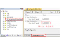 FreeRTOS 动态内存管理2024年11月12日 448
 -
一款常用buffer程序2024年11月06日 88
-
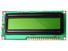 1602液晶显示模块的应用2012年08月03日 192
 -
GNU C 9条扩展语法2024年11月18日 261
-
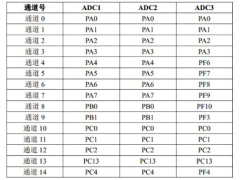 如何实现STM32F407单片机的ADC转换2024年11月15日 300
 -
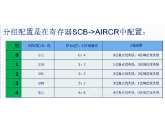 STM32使用中断屏蔽寄存器BASEPRI保护临界段2024年11月15日 195
-
C99语法规则2024年11月16日 675
-
 51单片机LED16*16点阵滚动显示2012年09月05日 664
 -
FreeRTOS 动态内存管理2024年11月12日 448
-
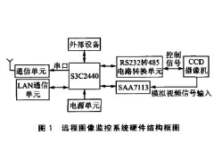 ARM9远程图像无线监控系统2012年07月03日 424
 -
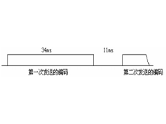 用单片机模拟2272软件解码2012年09月06日 300
 -
如何实现STM32F407单片机的ADC转换2024年11月15日 300
-
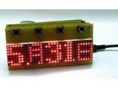 新颖的单片机LED钟2012年08月06日 278
 -
GNU C 9条扩展语法2024年11月18日 261